

What’s up?
This post is to show how I created a Java Duke Servo demo with a Raspberry Pi. This is another blog about Java on Raspberry Pi.
Interfacing a Servo Motor with Raspberry Pi is an interesting topic as Servo Motors are the main components of a Robot and with the help of Raspberry Pi, you can have endless opportunities in Robotics.
Because today we celebrate children’s day in Brazil, I came with the idea to show this simple robot example using a servo motor and a Raspberry Pi. And nothing better than a Java Duke servo demo to show Java on Raspberry Pi.
Components
- SG90 Micro-servo motor
- Jumper wires (generic)
- Raspberry Pi 3b or Arduino
Idea
Using a cardboard and Duke image to create a servo demo where Duke moves his arm.

I used this image to create my demo.
Control a Servo Motor
To control a Servo Motor, you need to use a technique called Pulse Width Modulation or PWM. In PWM technique, you will be sending a pulse of variable width and the position of the Servo Motor’s shaft will be set by the width or length of the Pulse.
Nice “Pulse Width Modulation” explanation here
The frequency of the PWM signal is a fixed value and is dependent on the type of Servo Motor.
At 50Hz i.e. a period of 20ms, the minimum pulse width is 1ms and the maximum pulse width is 2ms. Most servo motors can have a swept area of 180 degrees i.e. 90 degrees on either side of the neutral position.
When the pulse width of the PWM Signal is 1ms, the position of the servo is the left. The Duty Cycle of this position is (1ms/20ms) x 100 = 5%.
Similarly, for pulse widths of 1.5ms and 2ms, the position of the servo is middle (with a duty cycle of 7.5%) and far right (with a duty cycle of 10%).
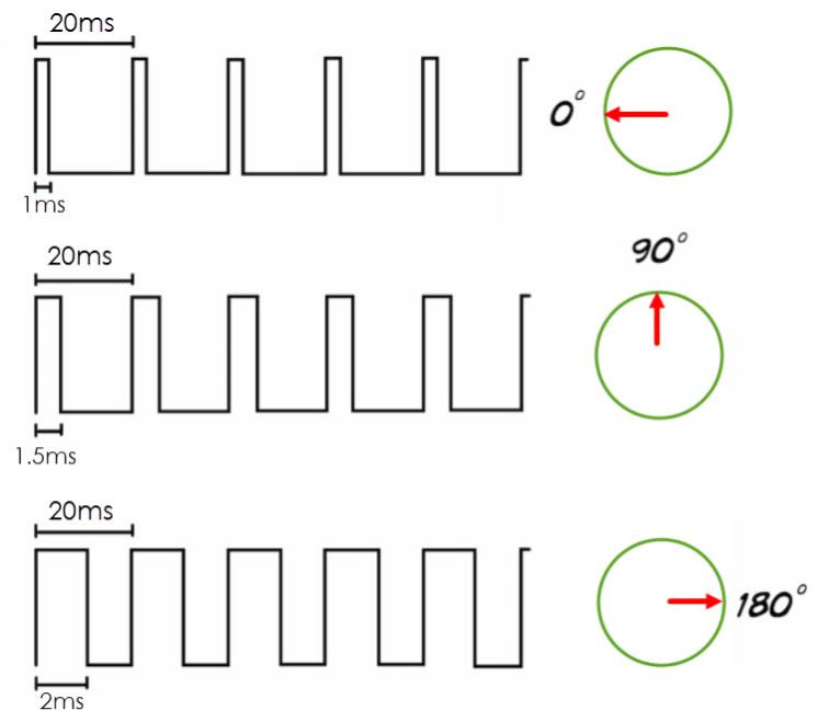
- so for 50hz, one frequency is 20ms
- duty cycle for 0 degree = (1/20)*100 = 5%
- duty cycle for 90 degree = (1.5/20)*100 = 7.5%
- duty cycle for 180 degree = (2/20)*100 = 10%
Note: Be aware here that you need to test and check your servo. You might need to calibrate this number for you.
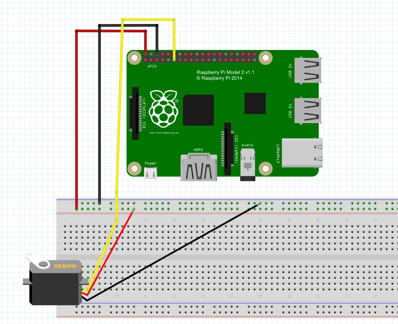
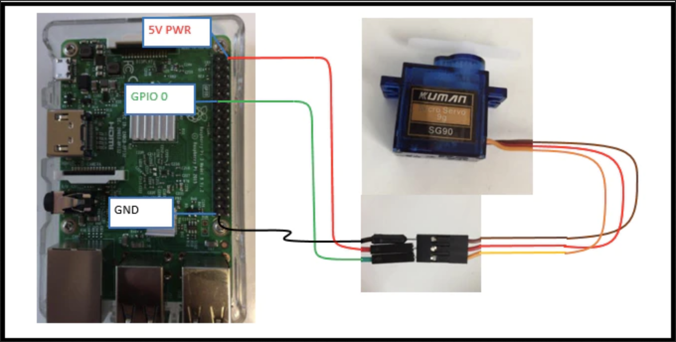
Schematics
I’m using the SG90 servo motor and you can check the Datasheet here.
The Tower Pro SG90 Servo Motor Consists of three Pins: PWM (Orange or Yellow), VCC (Red), and GND (Brown). The VCC and GND pins must be connected to +5V and GND of the power supply.
PWM or Signal Pin of the Servo Motor must be connected to the PWM Output of the Controller (Raspberry Pi). Based on the width of the Pulses from the PWM signal, the angle of the Servo Motor’s shaft will vary.
1ms pulse for 0 degree (LEFT)
1.5ms pulse for 90 degree (MIDDLE)
2ms pulse for 180 degree (RIGHT)
PI4J
1 2 3 4 5 6 7 8 9 10 11 12 13 14 15 16 17 18 19 20 21 22 23 24 25 26 27 28 29 30 31 32 33 34 35 36 37 38 39 40 41 42 43 44 45 46 47 48 | import com.pi4j.io.gpio.GpioController; import com.pi4j.io.gpio.GpioFactory; import com.pi4j.io.gpio.GpioPinPwmOutput; import com.pi4j.io.gpio.Pin; import com.pi4j.io.gpio.RaspiPin; import com.pi4j.util.CommandArgumentParser; public class TestPwmServoMotor { public static void main(String[] args) throws InterruptedException { pwm(args); } /** * @param args * @throws InterruptedException */ public static void pwm(String[] args) throws InterruptedException{ final GpioController gpio = GpioFactory.getInstance(); Pin pin = CommandArgumentParser.getPin( RaspiPin.class, RaspiPin.GPIO_00, args); GpioPinPwmOutput pwm = gpio.provisionSoftPwmOutputPin(pin); pwm.setPwmRange(100); int sleep = 1000; for(int i = 0 ;i<10;i++){ pwm.setPwm(25); System.out.println("PWM rate is: " + pwm.getPwm()); Thread.sleep(sleep); pwm.setPwm(15); System.out.println("PWM rate is: " + pwm.getPwm()); Thread.sleep(sleep); pwm.setPwm(6); System.out.println("PWM rate is: " + pwm.getPwm()); Thread.sleep(sleep); } gpio.shutdown(); System.out.println("pwm end"); } } |
Python
1 2 3 4 5 6 7 8 9 10 11 12 13 14 15 16 17 18 19 20 21 22 23 24 25 | import RPi.GPIO as GPIO import time control = [5,5.5,6,6.5,7,7.5,8,8.5,9,9.5,10] servo = 22 GPIO.setmode(GPIO.BOARD) GPIO.setup(servo,GPIO.OUT) p=GPIO.PWM(servo,50) p.start(2.5) try: while True: for x in range(11): p.ChangeDutyCycle(control[x]) time.sleep(0.03) print x for x in range(9,0,-1): p.ChangeDutyCycle(control[x]) time.sleep(0.03) print x except KeyboardInterrupt: GPIO.cleanup() |
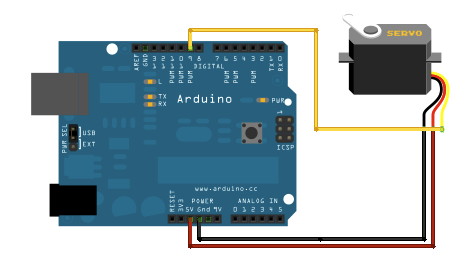
Arduino
And of course, you can do this demo with an Arduino as well.
1 2 3 4 5 6 7 8 9 10 11 12 13 14 15 16 17 18 19 20 21 22 23 24 25 26 | #include <Servo.h> Servo servo void setup() { servo.attach(9); } void loop() { servo.write(0); delay(500); delay(10000); servo.write(90); delay(500); delay(10000); servo.write(180); delay(500); delay(10000); servo.write(90); delay(500); delay(10000); servo.write(0); delay(500); delay(10000); } |
Results
The next steps are to create a code that transforms text into the flag language
Links
https://pi4j.com/1.2/index.html
http://www.ee.ic.ac.uk/pcheung/teaching/DE1_EE/stores/sg90_datasheet.pdf
https://en.wikipedia.org/wiki/Pulse-width_modulation
https://www.electronics-tutorials.ws/blog/pulse-width-modulation.html